|
|
|
|
The ATM standard does not specify any particular routing algorithm, so the carrier is free to chose among the different algorithms.
ATM layer routing is based on the VPI field, not on the VCI field, except at the final hop in each direction, when cells are sent between a switch and a host. Between two switches, only the virtual path is used.
Let us now see how cells could be routed within an interior switch (one that is attached only to other switches and not to hosts). Let us consider a concrete example, the Omaha switch in Fig. 5-66. For each of its five incoming lines, it has a table, vpi_table, indexed by incoming VPI that tells which of five outgoing lines to use and what VPI to put in outgoing cells. Let us assume the five lines are numbered from 0 to 4, as in the figure. For each outgoing line, the switch maintains a bit map telling which VPIs are currently in use on that line.

Fig. 5-66. Rerouting a virtual path reroutes all of its
virtual circuits.
When the switch is booted, all the entries in all vpi_table structures are marked as not in use. Similarly, all the bit maps are marked to indicate that all VPIs are available (except the reserved ones). Now suppose calls come as shown in Fig. 5-67.
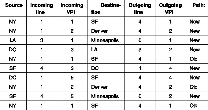
Fig. 5-67. Some routes through the Omaha switch of Fig. 5-66.
As each virtual path (and virtual circuit) is set up, entries are made in the tables. We will assume the virtual circuits are full duplex, so that each one setup results in two entries, one for the forward traffic from the source and one for the reverse traffic from the destination.
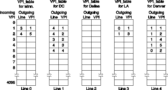
Fig. 5-68. Table entries for the routes of Fig. 5-66.
The tables corresponding to the routes of Fig. 5-67 are shown in Fig. 5-68. For example, the first call generates the (4,1) entry for VPI 1in the DC table because it refers to cells coming in on line 1 with VPI 1 and going to SF. However, an entry is also made in the Denver table for VPI 1 showing that cells coming in from Denver with VPI 1 should go out on line 1with VPI 1. These are cells traveling the other way (from SF to NY) on this virtual path. Note that in some cases two or three virtual circuits are sharing a common path. No new table entries are needed for additional virtual circuits connecting a source and destination that already have a path assigned.
Now we can explain how cells are processed inside a switch. Suppose that a cell arrives on line 1 (DC) with VPI 3. The switch hardware or software uses the 3 as an index into the table for line 1 and sees that the cell should go out on line 3 (LA) with VPI 2. It overwrites the VPI field with a 2 and the switch gets the cell from its current input buffer to line 3.
At this point it is straightforward to see how an entire bundle of virtual circuits can be rerouted, as is done in Fig. 5-66. By changing the entry for VPI 1 in the DC table from (4,1) to (3,3), cells from NY headed for SF will be diverted to LA. Of course, the LA switch has to be informed of this event, so the switch has to generate and send a SETUP message to LA to establish the new path with VPI 3.Once this path has been set up, all the virtual circuits from NY to SF are now rerouted via LA, even if there are thousands of them. If virtual paths did not exist, each virtual circuit would have its own table entry and would have to be rerouted separately.
The discussion above is about ATM in WANs. In a LAN, matters are much simpler.
3.3.4. Service Categories
ATM networks offers the following service categories:

Fig. 5-69. The ATM service categories.
The properties of various service categories are summarized in Fig. 5-70.

Fig. 5-70. Characteristics of the ATM service categories.
Quality of service is an important issue for ATM networks, in part because they are used for real-time traffic such as audio and video. The customer and the network operator or carrier must agree on a contract defining the service.
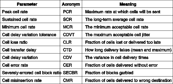
Fig. 5-71. Some of the quality of service parameters.
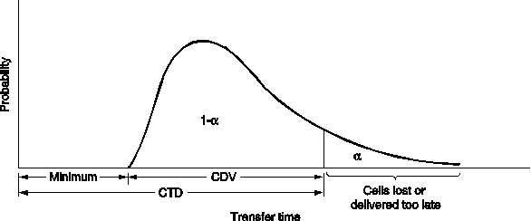
Fig. 5-72. The probability density function for cell arrival times.
The contract between the customer and the carrier has three parts:
The contract may be different for each direction. For a video-on-demand application, the required bandwidth from the user's remote control to the video server might be 1200 bps. In the other direction it might be 5Mbps.
To make it possible to have concrete traffic contracts, the ATM standard defines a number of QoS (Quality of Service) parameters whose values the customer and carrier can negotiate. The most important ones are the following:
The first three parameters specify how fast the user wants to send.
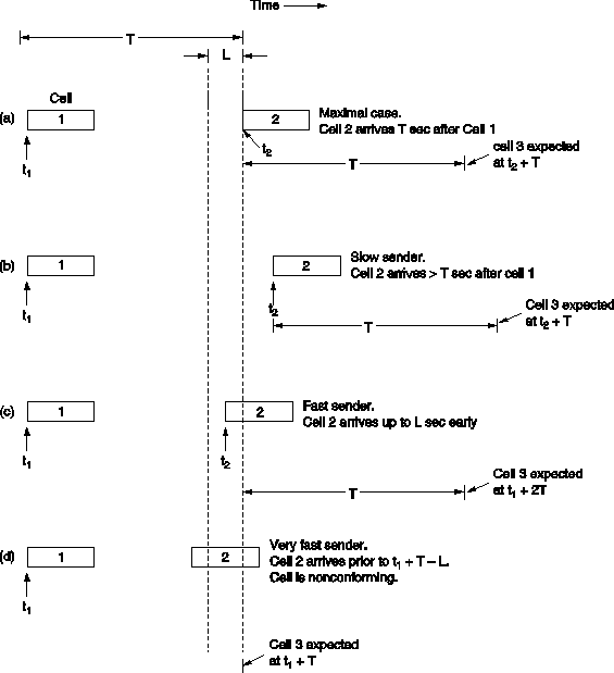
Fig. 5-73. The generic cell rate algorithm.
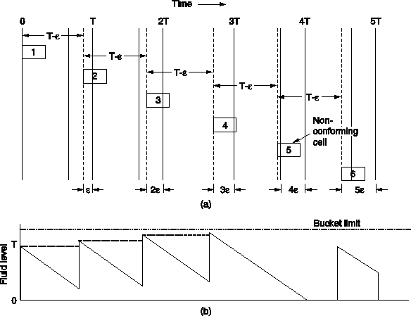
Fig. 5-74. (a) Sender trying to cheat. (b) The same cell
arrival pattern, but now viewed in terms of a leaky bucket.
The next three parameters describe characteristics of the network and are measured at the receiver.
The last three parameters specify characteristics of the network. They are generally not negotiable.
The third part of the traffic contract tells what constitutes obeying
the rules (e.g., if the customer sends one cell too early, does this
void the contract? Or, if the carrier fails to meet one of its quality
targets for a period of 1 msec, can the customer sue?). So, this part
of the contract says how strictly the first two parts will be enforced).
3.3.6. ATM LANs
As it becomes increasingly obvious that replacing the public switched telephone network by an ATM network is going to take a very long time, attention is shifting to the use of ATM technology to connect existing LANs together. In this approach, an ATM network can function either as LAN, connecting individual hosts, or as a bridge, connecting multiple LANs.
The major problem that must be solved is how to provide connectionless LAN service over a connection-oriented ATM network. One possible solution is to introduce a connectionless server into the network. Every host initially sets up a connection to this server, and sends all packets to it for forwarding. While simple, this solution does not use the full bandwidth of the ATM network, and the connectionless server can easily become a bottleneck.
An alternative approach, proposed by ATM Forum is shown in Fig. 5-76. Here every host has a (potential) ATM virtual circuit to every other host. To send a frame, the source host first encapsulates the packet in the payload field of an ATM AAL message and sends it to the destination, the same way frames are shipped over Ethernet and other LANs.

Fig. 5-76. ATM LAN emulation.
The main problem introduced by this scheme is how to tell which IP (or other network layer address) belongs to which virtual circuit. At Ethernet, the problem is solved by ARP protocol using broadcasting, but this does not work with ATM LANs because they do not support broadcasting.
This problem is solved by introducing a new server, the LES (LAN Emulation Server). To look up a network layer address, a host send a packet to the LES, which then looks up the corresponding ATM address and returns it to the machine requesting it.
Some programs use broadcasting or multicasting as an essential part of the application. For these applications, the BUS (Broadcast/Unknown Server) is introduced. It has connection to all hosts and can simulate broadcasting by sending a packet to all of them.
A model similar to this one has been adopted by the IETF (Internet Engineering Task Force) as the official Internet way to use an ATM network for transporting IP packets. In this model the LES server is called ATMARP server. Broadcasting and multicasting are not supported in the IETF proposal. The model is described in RFC 1483 and RFC 1577.
In the IETF method, a set of ATM hosts can be grouped together to form a logical IP subnet (LIS). Each LIS has its own ATMARP server. In effect, a LIS acts like a virtual LAN. Hosts on the same LIS may exchange IP packets directly, but hosts on different ones are required to go through a router. The reason for having LISes is that every host on a LIS must (potentially) have an open virtual circuit to every other host on its LIS. By restricting the number of hosts per LIS, the number of open virtual circuits can be reduced to a manageable number.
Another use of ATM networks is to use them as bridges to connect existing LANs. In this configuration only one machine on each LAN needs an ATM connection.
ATM LAN emulation is an interesting idea, but there are serious questions about its performance and price, and there is certainly heavy competition from existing LANs and bridges, which are well established and highly optimized. Whether ATM LANs and bridges ever replace them remains to see.